OpenQuadruped
I architected a 3D-printed quadrupedal robot dog from scratch.
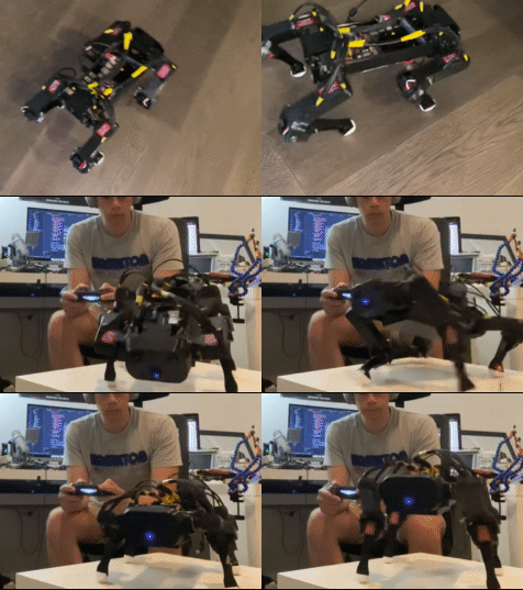
Presentation
I gave this R&D presentation about my OpenQuadruped project during my time working at Formlabs. If you'd rather a visual presentation as an overview of this project, you can find it below:
Controllability
My first milestone was deriving a full inverse kinematics model for a 3 DOF (degree of freedom) leg with various joint offsets that would allow me to simplify my design. In essence, an Inverse Kinematics (IK) model attempts to convert some intuitive domain, like xyz cartesian coordinate system, into directly useful values, like motor angles. To help you visualize, here’s a diagram from the paper I wrote about the IK model I derived.
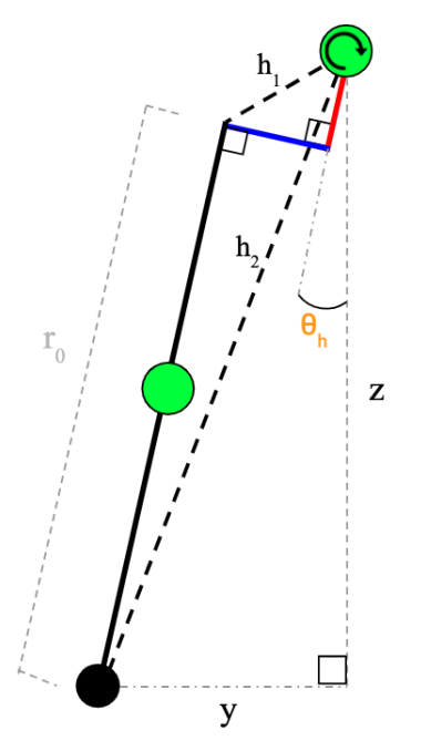
I ended up writing a small paper on the full derivation for documentation and reference, and I also made a visualization tool to illustrate the IK model at work:
Mechanical Design
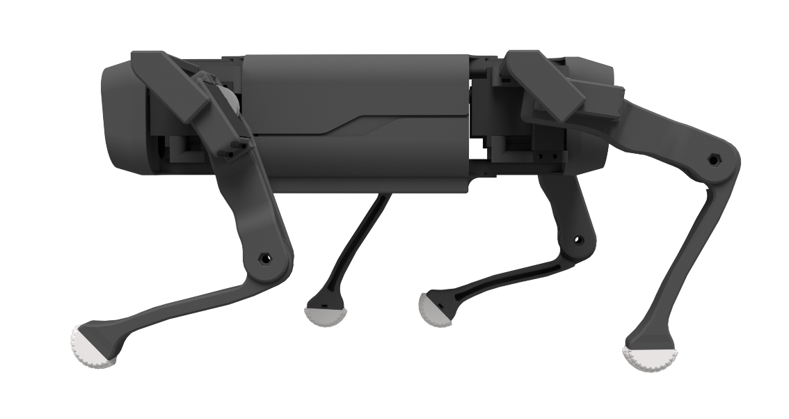
Then, I designed and 3D printed my first design what I now call MK1. This design was riddled with many problems. At heart, I’m much more of a computer science person than I am an electrical engineering one. And I’m both of those 10x more than I am a mechanical engineer. So, I had a lot to learn and tweak my design about 2 times before I realized that some of the design problems were too big to be ‘tweaked’, and I needed a design overhaul. I then spent about a month redesigning a lot of the major parts to address backlash and reduce moment forces on joints. Here’s the design I converged on:
Electronics
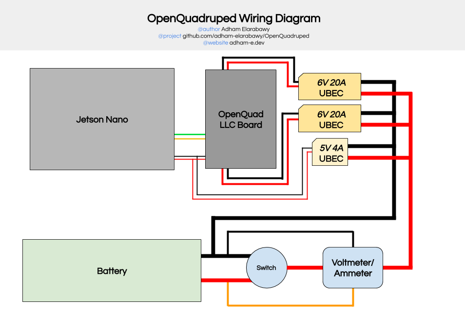
To handle all the power distribution & signal processing, I created a PCB that handled all of the low-level hardware control and interfaced with a Jetson Nano over serial.

I also created a full wiring schematic to help other people create their own versions of my dog:
Software
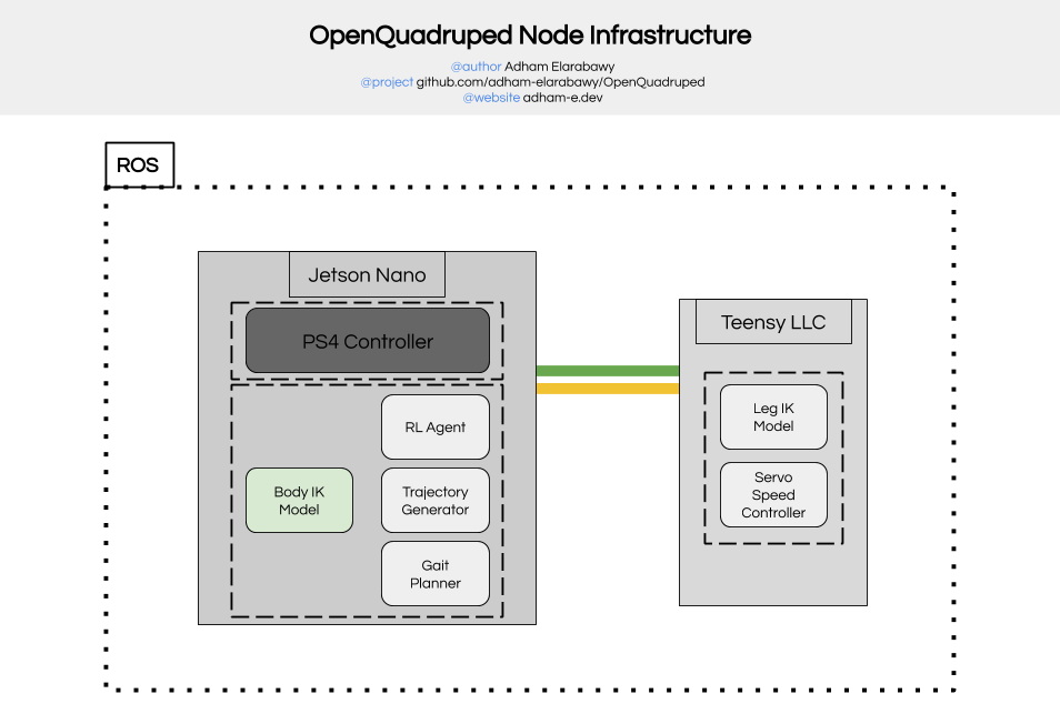
Since there are multiple processors handling the low-level control and high-level path planning and gait generation, and since both processors need to interface with each other, I utilized the ROS infrastructure to handle all the interfacing between concurrent processes. This design decision resulted in a much simpler debugging process, and I wholely attribute it to Maurice Rahme's technical guidance (More on that in the Collaboration + Conclusion section in the end).
To visualize all the concurrent processes that run on this dog, I created the following diagram:
Technical Explanation
To clarify exactly what is happening on the Jetson Nano: currently there can only be 1 of two main control processes running at a time on the jetson, based on the desired robot output. The first control process is the body IK model, which takes in the desired static yaw/pitch/roll/xyz within the scope of the body, and returns the hip-to-leg vectors (aka the xyz coordinates of each leg relative to the hip location). This is for static manipulation of the body's pose (when it isn't walking). The second control process is the RL Agent (which takes in IMU values and passes them through a matrix to figure out control parameters for foot clearance, etc to increase robustness) which feeds into the foot path planner (a 12-point bezier curve), which is then passed into the gait planner which time-parameterizes the aforementioned foot path into a trajectory for each foot. Now, we have a trajectory for a foot to follow that we can sample with real-time. However, we don't want all the feet to move at the same exact time or even in the same direction. What I then do is apply the phase offsets for each leg (which define the gait), which simply offsets the sample time by a factor of the stride period. I also rotate each leg's trajectory about the z axis based on user input from the controller. Now that I have a trajectory, I simply sample it with ROS time and send the resulting xyz points for each respective leg to the LLC controller (teensy). The main point here is that no matter which control process is running, the output of the jetson nano to the teensy is a set of xyz points (or hip-to-foot vectors if you want to think about it that way) that need to be converted somehow into motor angles.
Once the teensy receives this information from the jetson nano using the rosserial package, the teensy runs the hip-to-foot vectors through the leg IK model, which outputs a set of joint angles for each leg. Then, the newly computed desired joint angles are sent to the servo speed controller, which compares the relative distance that each servo needs to move and scales the corresponding joint speed in order to reduce unwanted body acceleration and to linearize motion. The servo speed controller is constantly running on the teensy LLC (low level controller), and the ROS topic simply updates the setpoints.
Due to the way that rosserial works, all the code running on the teensy must be encapsulated within a single node, so I just treat the teensy as a single node altogether.
Collaboration + Conclusion
At this point, I had already learned and refined so many skills: I created a custom PCB, improved my CAD skills, formalized my documentation, collaborated with a masters student, and maintained an open-source project.
One of the most rewarding things in this entire project was collaborating with Maurice Rahme, a new Boston Dynamics engineer! Check him out here.
More information:
You can find much more technical information about this project on my github repo. I also wrote this whitepaper on my custom 12DOF Inverse Kinematic Model that accounts for the various joint offsets in my design.
In the meantime, you can also take a look at some of the demo videos I've uploaded to youtube about my robot dog!